7-48 Draw the Shear and Moment Diagrams for the
170 C HAPTER 4I NTERNAL Fifty OADINGS D EVELOPED IN S TRUCTURAL M EMBERS
four
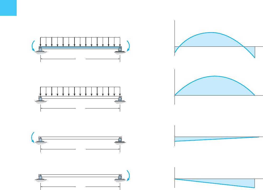
In a similar manner, nosotros can also simplify structure of the
"resultant" moment diagram for a beam by using a superposition of
"simply supported" beams. For example, the loading on the beam shown
at the pinnacle of Fig. 4–22a is equivalent to the beam loadings shown beneath
it. Consequently, the separate moment diagrams for each of these three
beams can be used rather than cartoon the resultant moment diagram
shown in Fig. 4–22b.
5 kN/ grand
12 grand
twenty kN 1000
40 kN chiliad
ⴝ
ⴙ
v kN/ yard
12 grand
ⴙ
12 thou
twenty kN 1000
12 g
40 kN chiliad
superposition of simply supported beams
(a)
Fig. 4–22
M (kN m)
twenty
xl
x (m)
resultant moment diagram
M (kN m)
x (m)
ⴝ
ⴙ
60.3
90
Thousand (kN chiliad)
x (grand)
–20
ⴙ
M (kN g)
ten (m)
40
superposition of associated moment diagrams
(b)
4.v GrandOMENT DIAGRAMS CONSTRUCTED BY THE METHOD OF SUPERPOSITION 171
four
Example four.16
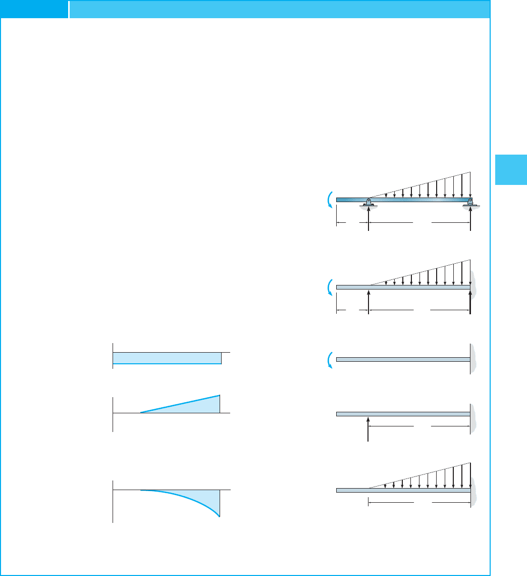
Draw the moment diagrams for the beam shown at the elevation of Fig. 4–23a
using the method of superposition. Consider the axle to be tin can-
tilevered from the support at B.
SOLUTION
If the beam were supported as a cantilever from B, information technology would be
subjected to the statically equivalent loadings shown in Fig. 4–23a.The
superimposed 3 cantilevered beams are shown below it together
with their associated moment diagrams in Fig. 4–23b. (As an help to
their construction, refer to Fig. iv–20.) Although not needed hither, the
sum of these diagrams will yield the resultant moment diagram for the
beam. For practice, endeavor drawing this diagram and cheque the results.
ⴙ
ⴙ
superposition of associated moment diagrams
(b)
M (k ft)
187.5
x (ft)
10 (ft)
x (ft)
Grand (thousand ft)
150
337.v
Fig. 4–23
22.v yard
15 ft
superposition of cantilevered beams
(a)
ⴙ
5 k/ ft
15 ft
5 k/ ft
5 thou/ ft
A
B
150 grand ft
150 k ft
v ft 15 ft
22.five k
15 m
5 ft fifteen ft
22.five thou
15 k
150 k ft
ⴝ
ⴙ
A
B
172 C HAPTER 4I NTERNAL 50 OADINGS D EVELOPED IN S TRUCTURAL Yard EMBERS
4
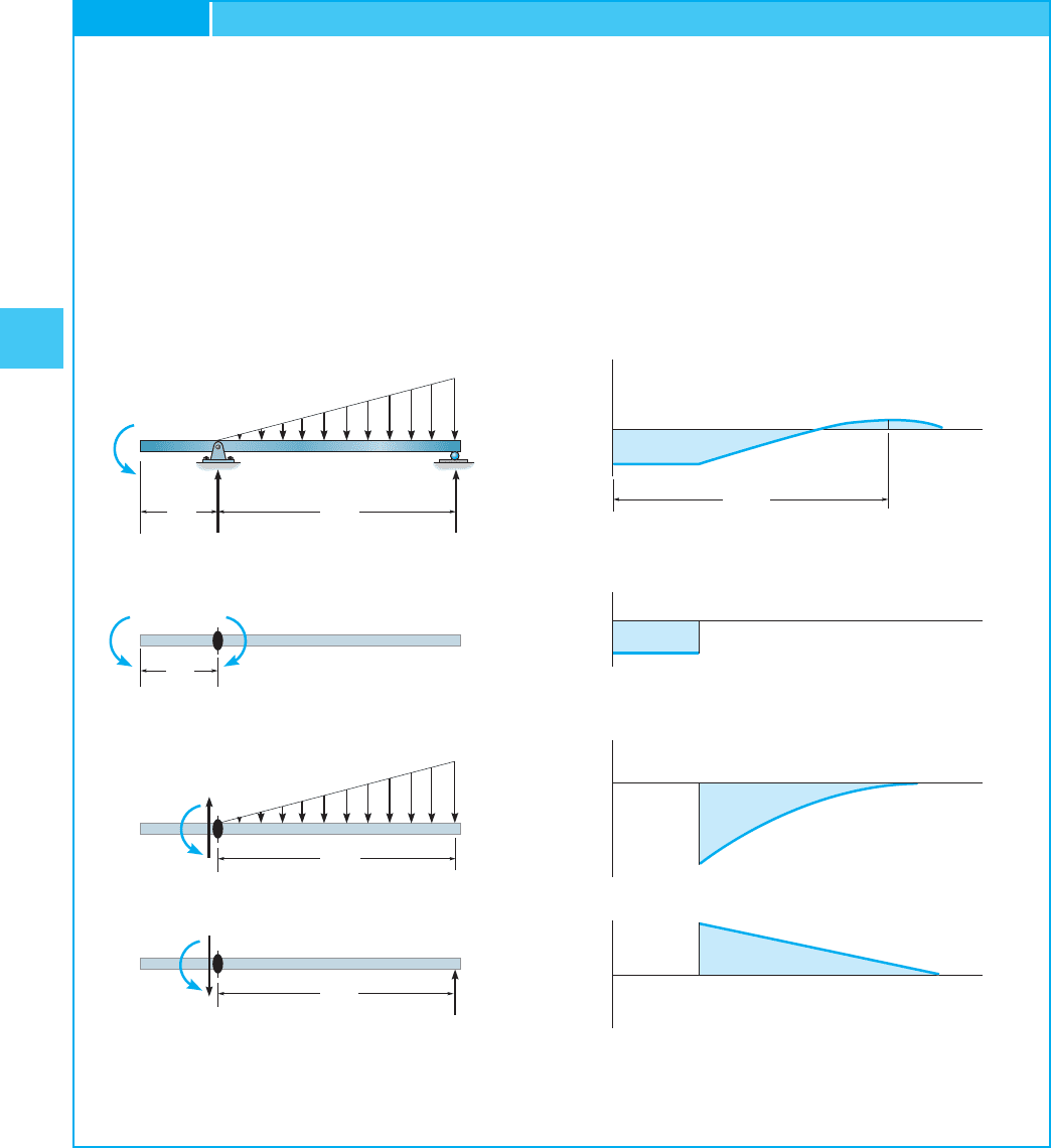
Draw the moment diagrams for the beam shown at the meridian of Fig. 4–24a
using the method of superposition. Consider the beam to be cantilevered
from the pivot at A.
SOLUTION
The superimposed cantilevered beams are shown in Fig. 4–24a
together with their associated moment diagrams, Fig. 4–24b. Notice
that the reaction at the pin (22.5 k) is not considered since it produces
no moment diagram. As an practice verify that the resultant moment
diagram is given at the top of Fig. 4–24b.
Instance 4.17
5 g/ ft
A
B
five 1000/ ft
15 k
15 thousand
superposition of cantilevered from A beams
(a)
B
225 k ft
37.5 k
ⴝ
ⴙ
ⴙ
15 ftfive ft
xv m
150 m ft
22.5 k
15 ft
375 g ft
five ft
150 k ft
150 grand ft
15 ft
Fig. 4–24
24.3
x (ft)
150
150
375
225
Chiliad (1000 ft)
M (k ft)
superposition of associated moment diagrams
b
ⴝ
ⴙ
ⴙ
x (ft)
M (k ft)
x (ft)
1000 (g ft)
x (ft)
16.6 ft

4.v MOMENT DIAGRAMS CONSTRUCTED By THE METHOD OF SouthUPERPOSITION 173
4
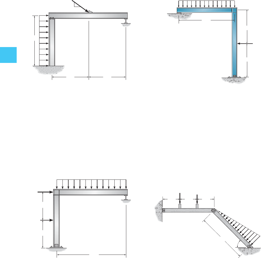
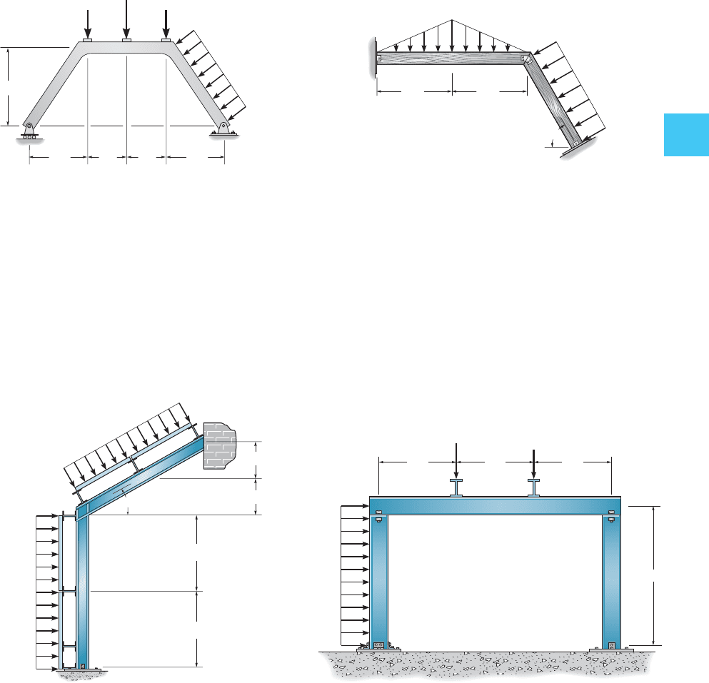
4–38. Depict the shear and moment diagrams for each of
the three members of the frame. Assume the frame is pin
connected at A, C, and D and there is a fixed articulation at B.
*four–40. Draw the shear and moment diagrams for each
member of the frame. Presume A is a rocker, and D is
pinned.
Issues
15 kN/ m
50 kN
forty kN
A
D
BC
1.5 thousand 1.5 1000 2m
four m
6m
A
B
C
D
0.6 k/ft
0.viii k/ft
20 ft
16 ft
2 k/ ft
8ft 4ft
15 ft
D
A
BC
4 chiliad
iii one thousand
Prob. 4–40
four–39. Draw the shear and moment diagrams for each
member of the frame. Assume the support at A is a pivot and
D is a roller.
4–41. Draw the shear and moment diagrams for each
member of the frame.Presume the frame is pin continued at
B, C, and D and A is fixed.
B
C
D
A
3 k
6 g vi k
3 k
15 ft
0.8 k/ft
8 ft
8 ft 8 ft
174 C HAPTER 4I NTERNAL L OADINGS D EVELOPED IN S TRUCTURAL Yard EMBERS
iv
four–42. Describe the shear and moment diagrams for each
member of the frame. Assume A is stock-still, the joint at B is a
pin, and support C is a roller.
*4–44. Draw the shear and moment diagrams for each
fellow member of the frame. Assume the frame is roller supported
at A and pin supported at C.
B
A
C
0.five grand/ft
20 thou
8 ft
6 ft
6 ft
3
4
5
Prob. 4–42
4 ft
fifteen 1000
4 thousand/ft
10 m
iv ft
10 ft
A
B
C
Prob. four–43
4–43. Depict the shear and moment diagrams for each
fellow member of the frame.Assume the frame is pin connected at
A, and C is a roller.
A
B
C
six ft
6 ft
10 ft
1.5 k/ ft
2 thousand
Prob. iv–44
four–45. Draw the shear and moment diagrams for each
member of the frame.The members are pivot connected at A,
B, and C.
45
A
B
C
fifteen kN
10 kN
4 kN/ m
2 grand 2 one thousand ii m
six one thousand
Prob. 4–45
4.five MOMENT DIAGRAMS CONSTRUCTED BY THE KETHOD OF SUPERPOSITION 175
4
4–46. Draw the shear and moment diagrams for each
member of the frame.
*4–48. Depict the shear and moment diagrams for each
member of the frame. The joints at A, B , and C are pin
connected.
300 lb/ ft
500 lb/ ft
A
B
C
thirty
7 ft
3.5 ft
3.5 ft
7 ft
Prob. iv–47
6 ft half-dozen ft
8 ft
120 lb/ft
250 lb/ft
A
B
C
sixty
Prob. 4–48
5 kN 5 kN
10 kN
ii kN/m
3 m 3 m
4 one thousand
2 m 2 m
A
B
C
D
Prob. 4–46
4–47. Draw the shear and moment diagrams for each
fellow member of the frame. Assume the joint at A is a pin and
support C is a roller.The joint at B is stock-still.The air current load is
transferred to the members at the girts and purlins from the
simply supported wall and roof segments.
A
B
D
C
6 k
0.8 k/ ft
3 one thousand
8 ft 8 ft 8 ft
fifteen ft
Prob. 4–49
4–49. Draw the shear and moment diagrams for each of
the three members of the frame. Assume the frame is pin
connected at B, C, and D and A is fixed.
176 C HAPTER 4I NTERNAL L OADINGS D EVELOPED IN S TRUCTURAL Chiliad EMBERS
4
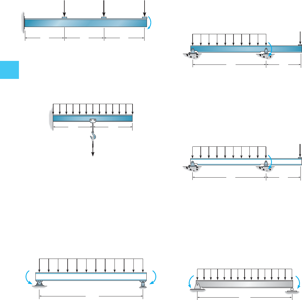
4–50. Draw the moment diagrams for the beam using the
method of superposition. The beam is cantilevered from A.
4–54. Describe the moment diagrams for the axle using
the method of superposition. Consider the beam to be
cantilevered from the pin support at A.
4–55. Describe the moment diagrams for the beam using
the method of superposition. Consider the axle to be
cantilevered from the rocker at B.
3 ft 3 ft3 ft
A
600 lb 600 lb 600 lb
1200 lbft
Prob. 4–50
80 lb/ft
12 ft12 ft
600 lb
Prob. 4–51
xx ft
150 lb ft150 lb ft
A B
250 lb/ ft
Probs. 4–52/4–53
4–51. Draw the moment diagrams for the beam using the
method of superposition.
*
4–52. Describe the moment diagrams for the beam using
the method of superposition. Consider the beam to exist
cantilevered from end A.
iv–53. Describe the moment diagrams for the beam using the
method of superposition. Consider the beam to be merely
supported at A and B as shown.
Probs. iv–54/4–55
30 kN
80 kN k
4 kN/ m
A
B
C
8 m 4 m
Prob. iv–56
30 kN
80 kN m
4 kN/ m
A
B
C
8 m 4 chiliad
4–57. Draw the moment diagrams for the beam using the
method of superposition. Consider the axle to be just
supported at A and B equally shown.
200 lb/ft
100 lbft 100 lbft
A
B
20 ft
Prob. iv–57
*4–56. Depict the moment diagrams for the beam using
the method of superposition. Consider the axle to exist
cantilevered from cease C.
PROJECT PROBLEMS 177
4
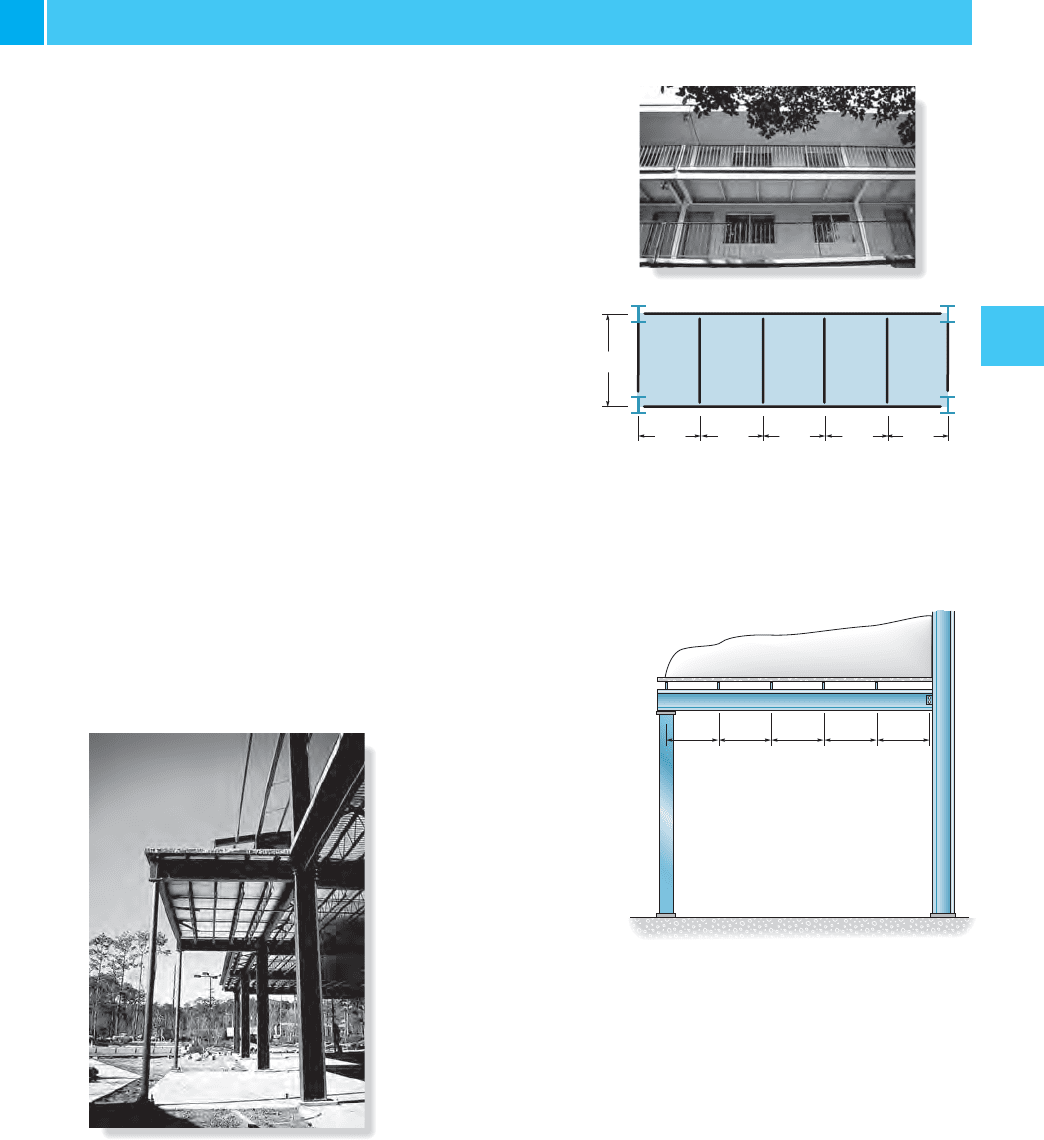
4–1P. The balustrade located on the third floor of a motel is
shown in the photo. It is synthetic using a four-in.-thick
concrete (plainly stone) slab which rests on the four simply
supported floor beams, two cantilevered side girders AB
and HG , and the front and rear girders. The idealized
framing programme with average dimensions is shown in the
adjacent effigy.According to local code, the balustrade live load
is 45 psf. Draw the shear and moment diagrams for the front end
girder BG and a side girder AB . Assume the front girder is a
aqueduct that has a weight of 25 lb兾ft and the side girders are
wide flange sections that have a weight of 45 lb兾 ft. Neglect
the weight of the flooring beams and front railing. For this
solution treat each of the v slabs as 2-way slabs.
PROJECT Bug
Prob. 4–1P
A
BCDEastwardF
H
G
six ft
iv ft
4 ft 4 ft iv ft 4 ft
4–2P. The canopy shown in the photo provides shelter
for the entrance of a building. Consider all members to be
simply supported. The bar joists at C, D, E, F each have a
weight of 135 lb and are xx ft long. The roof is four in. thick
and is to exist patently lightweight concrete having a density of
Live load acquired by drifting snow is assumed to
be trapezoidal, with sixty psf at the right (against the wall)
and 20 psf at the left (overhang). Assume the concrete slab
is merely supported between the joists. Draw the shear and
moment diagrams for the side girder AB . Neglect its
weight.
102 lb> ft
three
.
1.5 ft ane.5 ft one.5 ft 1.5 ft 1.five ft
A
CDE F
B
Prob. 4–2P
178 C HAPTER 4I NTERNAL L OADINGS D EVELOPED IN S TRUCTURAL M EMBERS
4
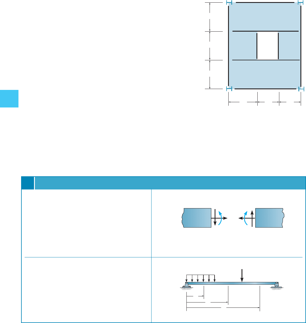
iv–3P. The idealized framing program for a floor system
located in the lobby of an office building is shown in the
figure. The floor is fabricated using 4-in.-thick reinforced rock
physical. If the walls of the lift shaft are fabricated from
iv-in.-thick lightweight solid physical masonry, having a
height of 10 ft, make up one's mind the maximum moment in beam
AB. Fail the weight of the members.
8 ft half-dozen ft 6 ft
viii ft
8 ft
8 ft
Elevator
shaft
AB
I
C
FH
GEast
D
Prob. four–3P
Structural members subjected to planar loads support
an internal normal forcefulness N, shear strength V, and bend-
ing moment M . To discover these values at a specific signal
in a fellow member, the method of sections must exist used.
This requires drawing a free-body diagram of a seg-
ment of the member, and then applying the three
equations of equilibrium.Always show the three inter-
nal loadings on the department in their positive directions.
The internal shear and moment tin be expressed as a
function of ten along the fellow member by establishing the
origin at a fixed point (normally at the left terminate of the
member, and and then using the method of sections, where
the section is made a altitude x from the origin). For
members subjected to several loads, dissimilar 10 coor-
dinates must extend between the loads
Chapter REVIEW
K
Northward
V
North
V
M
positive sign convention
P
westward
ten
1
10
2
ten
3
CHAPTER REVIEW 179
4
Shear and moment diagrams for structural members can be fatigued by plotting the shear and moment functions. They as well
can be plotted using the two graphical relationships.
Gradient of
Moment Diagram
f = 5Shear
dM
dx
= V
Slope of
Shear Diagram
f = e
Intensity of
Distributed Load
dV
dx
= w(ten)
Change in
Moment
f = eastward
Surface area under
Shear Diagram
¢ M =
L
V(x)
dx
Change in
Shear
f =
50
Area under
Distributed Loading
Diagram
¢ V =
50
w(x) dx
Note that a indicate of zero shear locates the point of maximum moment since . V = dM > dx = 0
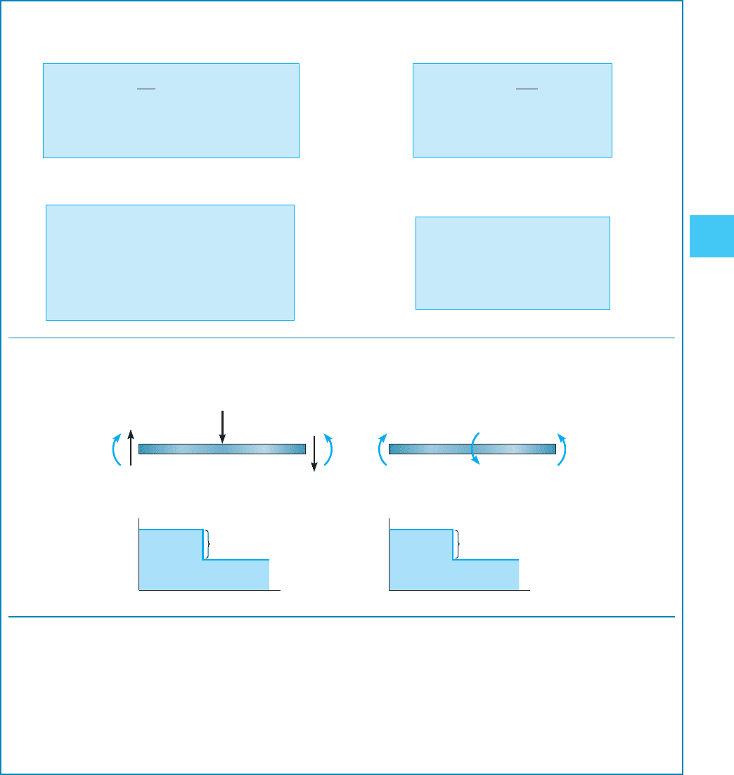
A force acting downward on the axle will cause the shear diagram to jump downwards, and a counterclockwise couple
moment volition cause the moment diagram to jump downwards.
Using the method of superposition, the moment diagrams for a fellow member tin can be represented past a series of simpler shapes.
The shapes represent the moment diagram for each of the separate loadings. The resultant moment diagram is then the
algebraic addition of the dissever diagrams.
One thousand
R
P
V
R
Yard
50
M
50
Five
L
5
L
VM
Five
R
xx
M
R
M¿
M
L
Thousand
R
Thousand¿ P
7-48 Draw the Shear and Moment Diagrams for the
Source: https://www.studmed.ru/view/hibbeler-rc-structural-analysis_5a1c4fe5e3d.html?page=20
0 Response to "7-48 Draw the Shear and Moment Diagrams for the"
Post a Comment